Configure the RTU
RTUs can be configured using the Trimble Unity web app. A pending configuration is created when configuring an RTU with the web app. This configuration is uploaded to the RTU during the next completed call. You can cancel a pending configuration anytime before the next call occurs. If you edit an RTU with a pending configuration, the edit screen will display the pending configuration rather than the active one.
|
|
 PREREQUISITES:
- Click the RTU you want to configure from the RTU list or select the assigned RTU from a monitoring site.
- Click Edit on the RTU details panel.

|
|
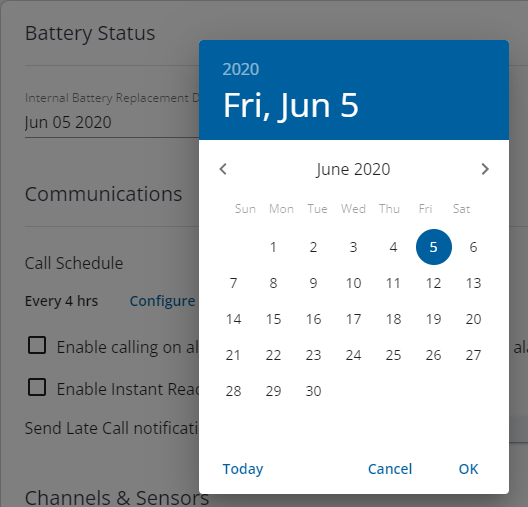
Setting the battery replacement date will reset the low battery warning and enable the system to estimate the battery percentage remaining more accurately.
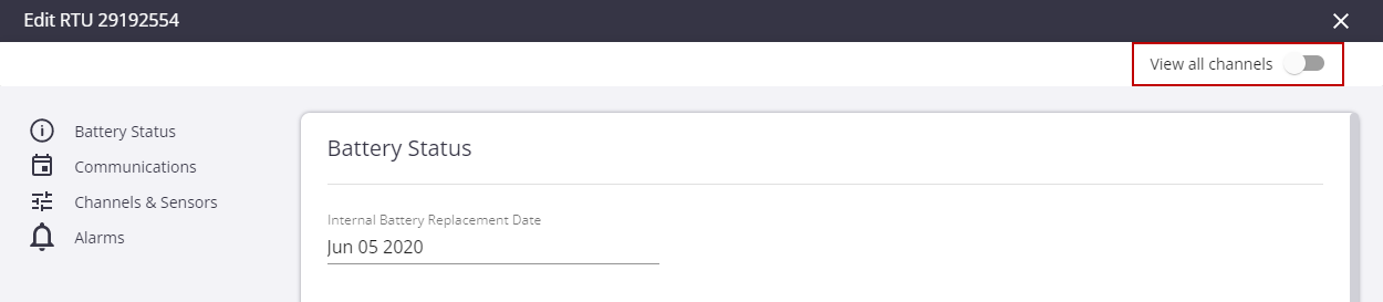
- In the Battery Status section, you can view the Internal Battery Replacement Date.
- If you have recently changed the battery, click the field and select the date it was changed from the calendar.
The RTU communications section configures why and how frequently the RTU calls into the system.
- In the Communications section, click Configure to open the Configure Call Schedule panel.
- Select By hours or By time of day. Enter the number of hours you want to pass between each call or enter the time of day you would like the RTU to call when configured to call once per day.
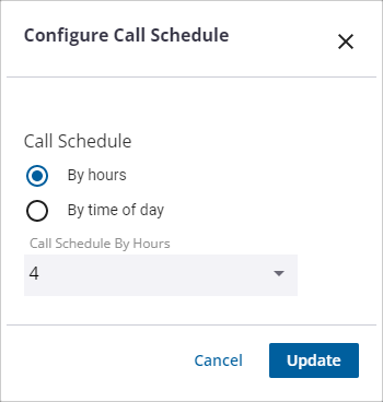
- Click Update to save the changes.
- Select the Modem Always-On check box to leave the cellular modem on to detect and answer incoming calls.
 NOTE: The Modem Always-On setting works with RU-35, RS-45, and R-3300 RTUs. These RTUs must be configured with a static IP address. Once enabled, users can place calls on-demand using the Call RTU option on a monitoring site details panel in the web and mobile versions. Leaving this feature enabled does result in significant battery usage. See About the Monitoring Site Details for more information.
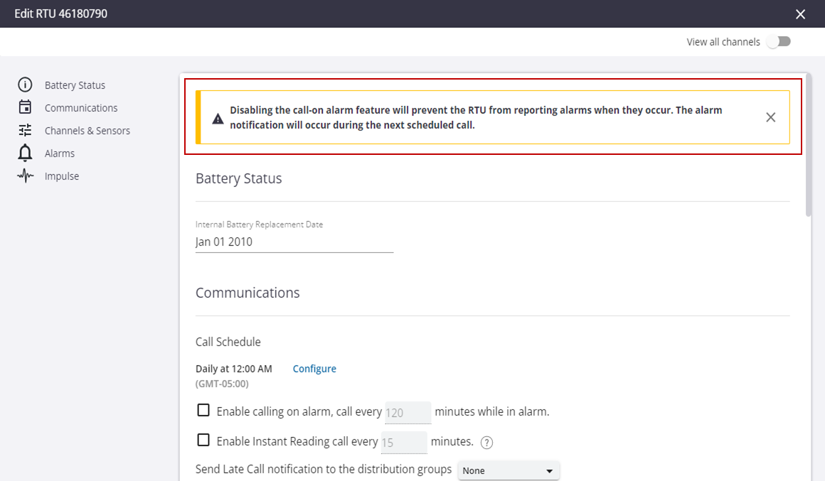
- Select the Enable calling on alarm, call every X minutes while in alarm check box to configure the RTU to call whenever an alarm starts or ends. The number of minutes indicates how often the RTU will call while it remains in alarm. Use this feature to collect data more frequently from a site while it remains in alarm.
|
|
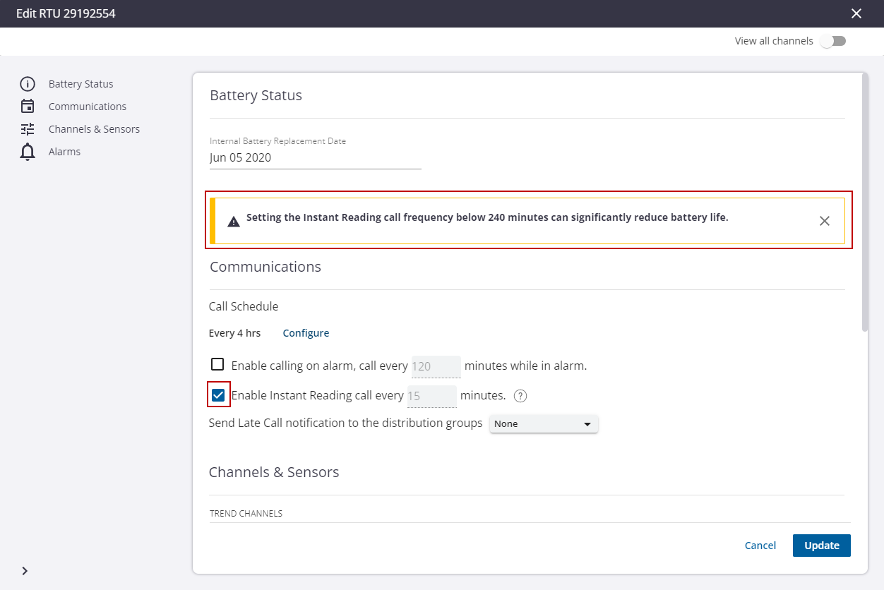
- Select the Enable Instant Reading call every X minutes check box to configure the RTU to make an instant reading call using the interval specified.
 TIP: Instant Reading is a supplemental call schedule that is fast to minimize battery drain and deliver the most recent data value. Any missing values are filled in during the next scheduled call.
- Select a distribution group from the Send Late Call notification to the distribution groups drop-down list to receive a notification when an RTU is late to call by more than four hours. This setting is only active when the RTU is assigned to a site.
|
|
The RTU configuration updates will be applied to the RTU the next time the RTU calls in.
Channels and sensors include all externally connected input signals that you wish to record. Channels are broken down into two types: Analog and Digital. Sensors are devices, often supplied by a third party, that sample input signals, process the sampled data, and provide results that are recorded by RTUs supporting smart sensor connections.
NOTE: The number and type of channels that can be configured depends on the type of RTU.
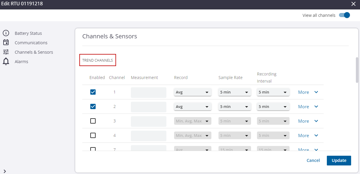
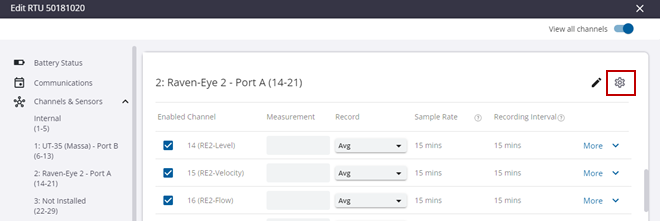
In the Channels and Sensors section, the channels are listed as well as the channel details.
- Toggle the View all channels switch to view all the channels including the channels that are disabled and sensors that are not installed.
The three available channel categories are Analog Channels, Digital Channels, and Event Channels.
 IMPORTANT: Undoing the pending configuration for an RTU does not undo changes made to measurements, including the name, type, and units.
Analog Channels: these channels sample electric current or voltage from the connected sensors and translate into data and measurements such as water level, pressure, and flow. The three configurable parameters of an analog channel are statistical data to record (average, minimum, and maximum), how often to sample the sensor, and how often to save or record the statistical data.
- Enabled: the channel is enabled.
- Channel: the channel number and select Channel Range is listed.
- Measurement: the measurement name of the channel.
- Record: the statistics being recorded. Click the Record drop-down list to select the data statistics you want to record (Min: minimum single sample, Avg: average of all samples, Max: maximum single sample).
- Sample Rate: how often you want the sensor to take a sample of the measurement. Click the Sample Rate drop-down list to select how often the sensor takes a sample.
NOTE: The sample rate is the rate at which the input signal is sampled. The sample rate requirements vary widely depending on the application. The most rapid sample rate available is once per second (except for sensors such as hydrant pressure recorders with impulse detection, which sample at a much higher rate). Note that the list of available sample rates is dependent upon the currently selected recording interval for the selected channel. Therefore, the longest sample rate is always equal to the currently programmed recording interval.
 BEST PRACTICE: If you are only using battery power to run your recorder, select the slowest sample rate that is consistent with your input signal. Battery life is dependent upon sampling frequency and higher frequency sample rates will reduce battery life.
- Recording Interval: how often the RTU records the samples. Click the Recording Interval drop-down list to select how often the data records the samples. That is, how often it records the chosen statistics. For example, for each recording interval it will record the average, minimum, and maximum for the samples taken during the recording interval.
NOTE: The recording interval is the frequency at which selected statistics are computed and stored into the recorder's permanent memory. You can select different recording intervals for each channel and the list of available recording intervals is dependent upon the currently selected sample rate for the selected channel. Recording intervals are always multiples of the sample rate.
BEST PRACTICE: If you are only using battery power to run your recorder, select the slowest recording interval that is consistent with your application as battery life is dependent upon the recording interval. Higher frequency recording intervals will reduce battery life.
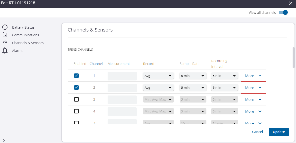
- Click More to open more configurations and settings for the channel.
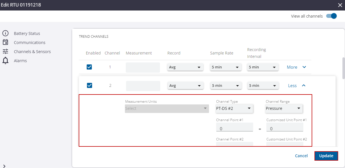
- Click the Measurement Units drop-down list to select the measurement unit for the channel. Changing the measurement type will update the measurement units to the default value for the selected type. You can override the default value if needed.
- Select a Channel Type from the drop-down list.
NOTE: Depending on the type of recorder you are working with, it may be possible to change the channel type for a specific channel. For example, channels 1–4 of the R-3307 recorder can be programmed to be either voltage channels or current inputs. For other recorders such as HPR-32A, which are measurement-type specific, there is only one channel type option: pressure. When changing channel types, if there are any required hardware modifications, a message alerts you of the necessary changes.
In the case of the R-3307, R-3314, and RS-45, changing from voltage to current requires that a switch setting be changed on the recorder. If the switch setting does not match the programmed channel type (for example, if the switch position is set to volts, but the software setting of the channel is set to current), then the channel does not record any data.
IMPORTANT: If the channel type is changed, the scaling for the channel must be modified as the old scaling information becomes invalid.
- Select a Channel Range from the drop-down list.
NOTE: Depending on the channel type, it may be possible to change the channel range of a selected channel. The possible ranges available are displayed in a drop-down list from which you can select the desired setting.
IMPORTANT: If the channel range is changed, the scaling for the channel must be modified as the old scaling information becomes invalid.
- If necessary, update the Channel Point and Channel Range fields to scale the sampled data to the desired recording units.
NOTE: Channel scaling determines how the actual analog signal (for example, voltage or current) is translated into a recognizable engineering unit as defined in the Measurement Units field (for example, PSI for pressure). The scaling is determined by supplying two points mapping a channel output value (for example, mA) to the relevant measurement value (for example, PSI). Typically, the two values supplied will mark the range of the channel (for example, 4 and 20 mA). To scale a 4 - 20 mA channel to record 0 to 100 PSI, enter the values 4 = 0 and 20 = 100 in the four fields provided. Scaling that results in a negative slope, such as when point 1 is greater than point 2, is invalid.
- Click the Measurement Type drop-down list to select the measurement type of the channel.
NOTE: Changing the measurement type will automatically update the units to match the default units of the selected type. The default unit selection can be overridden with the desired units.
- Click the Measurement Units drop-down list to select the measurement unit for the channel.
NOTE: Some fields, such as Measurement, Measurement Type, and Measurement Units, are disabled for channels without an assigned measurement. After an RTU is programmed with the updated configuration, measurements are automatically created during the next call.
- Click Update.
The digital channels may interface either uncommitted mechanical contacts such as switches or relay contacts, actively driven logic, or transistor inputs. They are configured for either pulse or event mode, depending on the channel type selected. Pulse mode is useful for counting the number of contact closures that occur during intervals. For example, it can count the number of times a tipping bucket rain gauge tips, accumulating the total interval rainfall. You must provide scaling that indicates how much each tip should be valued.
When interfacing mechanical contacts, selecting the low-speed pulse input employs a 3 millisecond bounce filter to eliminate false counts due to switch bounce. The high-speed pulse choice does not employ an input filter and should be selected when monitoring rapid pulse sources such as turbine meters or radiation counters.
Event mode records the date and time, to one second resolution, of contact closures and openings or the positive and negative transition of an analog logic signal. This mode is useful for recording pump starts or logging other critical events, such as float switch alarms and power failures.
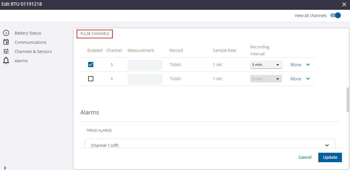
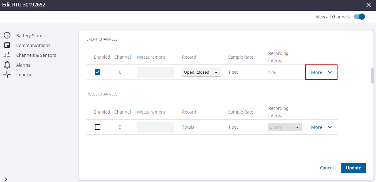
Pulse Channels
Pulse Channels: these channels count pulses from a source and translate the totals into data and measurements such as total rain fall or total consumption from water meters. The parameter to configure is how often to record the total pulses.
- Enabled: the channel is enabled.
- Channel: the channel number and select Channel Range is listed.
- Measurement: the measurement name of the channel.
- Record: the measurements being recorded. This is preconfigured to record Totals and cannot be modified.
- Sample Rate: N/A. This setting is unavailable for Pulse channels.
- Recording Interval: how often the RTU records the total number of pulses. Click the Recording Interval drop-down list to select how often the data records the samples.
NOTE: The recording interval is the frequency at which selected statistics are computed and stored into the recorder's permanent memory. You can select different recording intervals for each channel and the list of available recording intervals is dependent upon the currently selected sample rate for the selected channel.
BEST PRACTICE: If you are only using battery power to run your recorder, select the slowest recording interval that is consistent with your application as battery life is dependent upon the recording interval. Higher frequency recording intervals will reduce battery life.
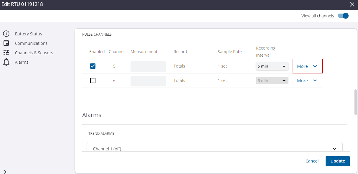
- Click More to open more configurations and settings for the channel.
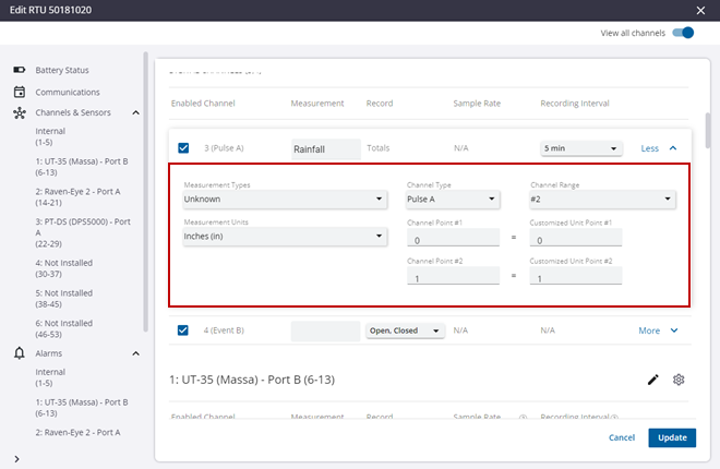
- Select a Channel Type from the drop-down list. A pulse channel can be switched between Pulse and Event modes.
NOTE: Pulse channels increment their pulse counter on the occurrence of a high (switch open) to low (switch closed) transition.
- Select a Channel Range from the drop-down list.
NOTE: Some RTUs support both a High Speed and Low Speed pulse input. In most cases, the Low Speed setting is preferred to eliminate extra counts caused by switch bounce.
IMPORTANT: If the channel range is changed, the scaling for the channel must be modified as the old scaling information becomes invalid.
- Click the Measurement Type drop-down list to select the measurement type of the channel.
NOTE: Changing the Measurement Type will automatically update the units to match the default units of the selected type. The default unit selection can be overridden with the desired units.
- Click the Measurement Units drop-down list to select the measurement unit for the channel.
NOTE: Some fields, such as Measurement, Measurement Type, and Measurement Units are disabled for channels without an assigned measurement. After an RTU is programmed with the updated configuration, measurements are automatically created during the next call.
- If necessary, update the Channel Point fields to scale the sampled data to the desired recording units.
NOTE: For pulse channels, you are counting the number of times a switch is opened or closed so you need to associate each time the switch is operated with a quantity of the defined measurement unit. For example, the "pulse" on a rain gauge is determined by an occurrence of the rain gauge bucket tipping and emptying. If a tipping occurrence is associated with a measurement of 0.01 inches of rain, and there are five occurrences of the tipping within a 10-minute recording interval, the total rainfall in the recording interval will be 0.05 inches, or will equate to a rate of 0.3 inches per hour, given the 10-minute recording interval. To scale a rain gauge where each tip equals 0.01 inches, enter the value 0 = 0 and 1 = 0.01 in the four fields provided.
- Click Update.
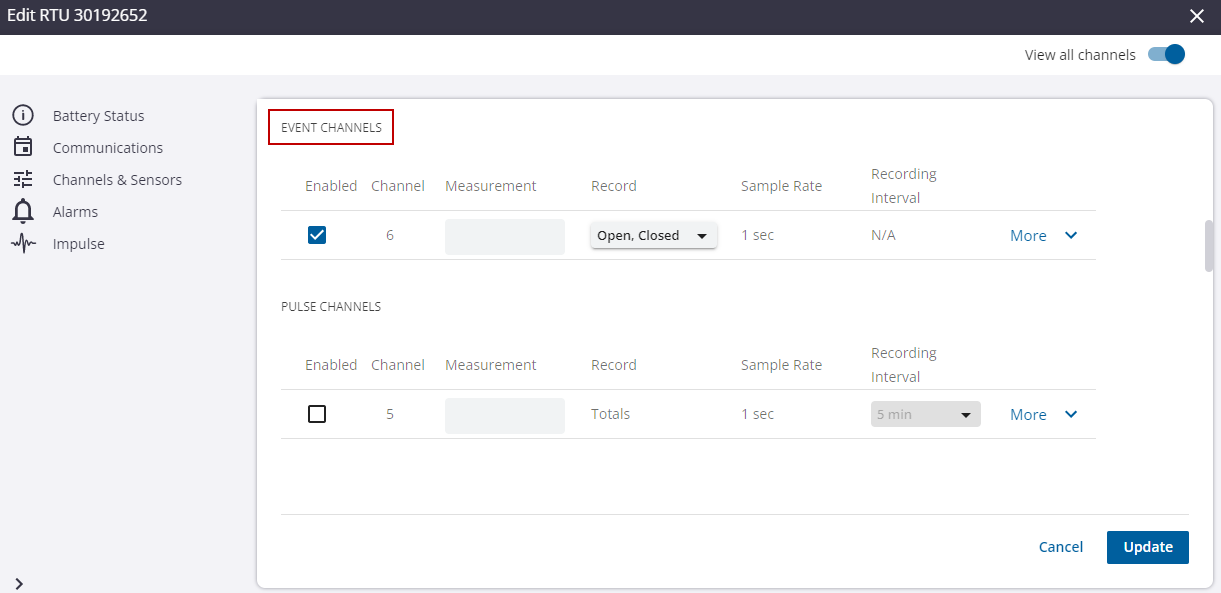
Event Channels
Event Channels: these channels do not record trending data over fixed intervals. Rather, they save discrete changes when switches close and open, and the time these events occur. These channels are typically used to alarm and monitor events such as pump starts, float switches, and power failures.
NOTE: Some RTUs, such as the R-3330 and RS-45, include dedicated event channels that only operate in event mode.
- Enabled: the channel is enabled.
- Channel: the channel number and select Channel Range is listed.
- Measurement: the measurement name of the channel.
NOTE: For event channels, the Measurement type is typically set to Event.
- Record: the measurements being recorded. Click the Record drop-down list to select the data you want to record. Open indicates when the switch opens or the device turns off, and Closed indicates when the switch closes or the device turns on.
NOTE: It is recommended that you always enable both the Open and Closed recording options for all event channels if you want to calculate any statistics, such as total on time.
- Sample Rate: N/A. This setting is unavailable for Event channels.
- Recording Interval: N/A. This setting is unavailable for Event channels.
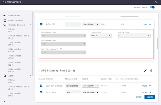
- Click More to open more configurations and settings for the channel.
- Select a Channel Type from the drop-down list. An event channel can be switched between Pulse and Event modes.
- Select a Channel Range from the drop-down list.
- Click the Measurement Type drop-down list to select the measurement type of the channel.
NOTE: Changing the Measurement Type will automatically update the units to match the default units of the selected type. The default unit selection can be overridden wit the desired units.
- Click the Measurement Units drop-down list to select the measurement unit for the channel.
- Click the Active State Indicated By drop-down list to select either Open or Closed.
TIP: The Active State will always be graphed and reported using the label On. The Measurement Units must be set to On/Off to enable the display.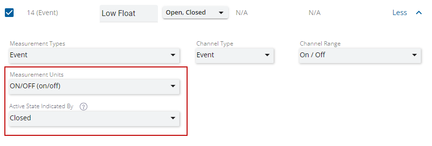
NOTE: Some fields, such as Measurement, Measurement Type, Measurement Units, and Active State Indicated By are disabled for channels without an assigned measurement. After an RTU is programmed with the updated configuration, measurements are automatically created during the next call.
- Click Update.
NOTE: Some RTUs such as the RS-45 contain event-only channels that are grouped separately from other digital channels.
Sensors are devices that communicate with the RTU using a standard hardware interface such as RS-232, RS-485, I2C, and SDI-12. These devices, sometimes called smart sensors, often perform their own input processing, providing the results to be recorded. They may require additional configuration using manufacturer software to permit them to communicate with the RTU.
Add a Sensor
In the Channels and Sensors section, the enabled channels and settings are listed as well as any configured sensors. The following steps are for adding a sensor to Ru-35 and RS-45 RTUs. The Ru-35 can be configured with up to six user-assignable sensors, and the RS-45 comes with three built-in sensors, one expansion sensor, and two user-assignable sensors.
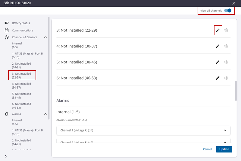
- Toggle the View all channels switch to view all the channels including the channels that are disabled.
NOTE: The channel fields are preconfigured based on the sensor type selected, but can be customized if needed.
- To edit a sensor, click the sensor from the Channels and Sensors list.
- Click the edit icon for the sensor you want to add.
BEST PRACTICE: Start with the first available sensor position.
- In the Edit Sensor panel, select the Sensor Name and the Sensor Port.
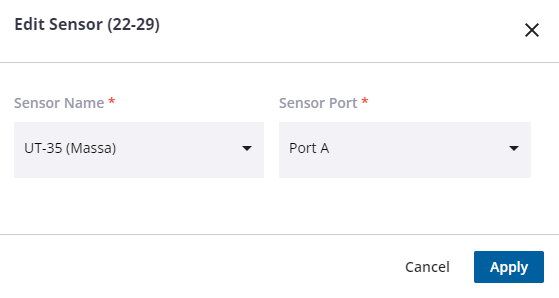
NOTE: The RTU sensor ports are labeled A and B. Select the port where the sensor is connected. You must acquire the appropriate cable for the sensor being connected. It is possible to connect multiple sensors to the same port using a Y cable.
- Click Apply.
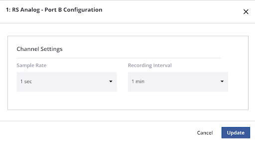
- To configure the sensor, click the gear icon.

- Select the Sample Rate and Recording Interval. Some sensors will contain additional settings that can be adjusted. See Sensor Configuration for more information.
- Click Update.
Remove a Sensor
- To remove a sensor, click the sensor from the Channels and Sensors list.
- Click the edit icon for the sensor you want to remove.

- Change the Sensor Name to Not Installed.
- Click Apply.
- Click Update.
Change a Sensor
- To change a sensor, click the sensor from the Channels and Sensors list.
- Click the edit icon for the sensor you want to change.
- Change the Sensor Name to the desired sensor type and update the Sensor Port if necessary.
- Click Apply.
- Click Update.
- To configure a sensor, click the sensor from the Channels and Sensors list.
- Click the gear icon to display the sensor settings.
- Select the Sample Rate and Recording Interval. Some sensors will contain additional settings that can be adjusted.
NOTE: All channels associated with a sensor share the same Sample Rate and Recording Interval.
- Click Apply.
- Click Update.
UT-35 Massa Ultrasonic Level Sensor
The Massa Ultrasonic Sensor can be used with RTUs that support smart sensors such as the Ru-35 and RS-45 RTUs. After adding the sensor, it needs to be configured. See Add a Sensor for more information.
- Click the gear icon next to the sensor name.
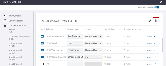
- Select the Sample Rate and Recording Interval
NOTE: All channels associated with a sensor share the same Sample Rate and Recording Interval.
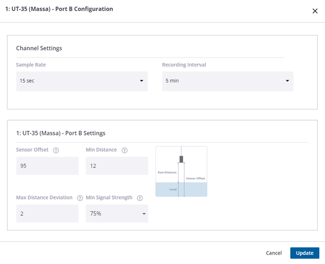
- Configure the sensor information by clicking within each field.
- Sensor Offset: The distance from the sensor to the bottom of the pipe, tank, or reservoir being monitored. This value must be greater than the Min Distance setting.
- Min Distance: The minimum acceptable distance that the sensor can accurately measure (Defaults: 12 inches for UT-35U 95 KHz and 4 inches for UT-35U 150 KHz).
- Max Distance Deviation: The maximum acceptable deviation between consecutive readings that will be accepted as valid data (Default: 2 inches).
- Min Signal Strength: The minimum acceptable reflection signal strength that will be recorded as valid data (Default: Disabled). You can set this value between 25% and 100% to improve data accuracy at the expense of data reliability.
- Click Update.
NOTE: Smart sensors that produce data in units other than voltage, current, and counts can be automatically scaled to other compatible units without the need to supply scale factors. For example, a sensor that reports in inches can be converted to feet or a flow meter that reports liters per minute can be converted to gallons per minute. When the measurement is created, the selected units are automatically assigned. A warning is displayed if the selected measurements are incompatible with the channel's units. The units are still accepted, but the conversion is not performed.
Raven-Eye 2 Noncontact Flow Meter
The Raven-Eye 2 Noncontact Flow Meter can be used with RTUs that support smart sensors such as the Ru-35 and RS-45 RTUs. It requires a separate level sensor, typically an Ultrasonic or a DT-PS (digital pressure sensor), to calculate flow. After adding the sensor, it needs to be configured. See Add a Sensor for more information.
- Click the gear icon next to the sensor name.
- Select the Sample Rate and Recording Interval.
NOTE: All channels associated with a sensor share the same Sample Rate and Recording Interval.
- Click Apply.
- Click the More button next to the RE2-Level channel.
- Click the Channel Range to select the channel number of the level data to supply to the flow meter.
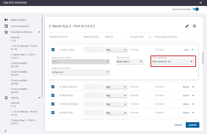
NOTE: When configuring the sensor, indicate which RTU channel supplies the level data to the flow meter by setting the Channel Range to the desired channel. In this example, channel 15 is selected. This channel is recommended when combining the Raven-Eye 2 in sensor position 1 with an ultrasonic level sensor in sensor position 2 or when applying the Ru-35 Raven-Eye 2 / UT-35 Ultrasonic template.
- Click Update.
NOTE: Smart sensors that produce data in units other than voltage, current, and counts can be automatically scaled to other compatible units without the need to supply scale factors. For example, a sensor that reports in inches can be converted to feet or a flow meter that reports liters per minute can be converted to gallons per minute. When the measurement is created, the selected units are automatically assigned. A warning is displayed if the selected measurements are incompatible with the channel's units. The units are still accepted, but the conversion is not performed.
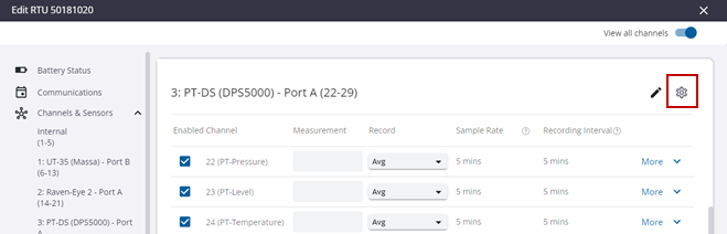
PT-DS (DPS5000)
The PT-DS Sensor can be used with RTUs that support smart sensors such as the Ru-35 and RS-45 RTUs. It is also compatible with the PR-32 and Ru-32 devices. After adding the sensor, it should be configured. See Add a Sensor for more information.
- Click the gear icon next to the sensor name.
- Select the Sample Rate and Recording Interval.
NOTE: All channels associated with a sensor share the same Sample Rate and Recording Interval.
- Click Apply.
- Set the Channel Points to apply a depth offset if required.
NOTE: When recording level, you can supply an offset to correct any differences between the sensor depth and the actual depth of a measured well or tank. In this example, an offset of 4 inches is applied by specifying 0 inches = 4 inches and 1 inch = 5 inches.
- Click Update.
NOTE: Smart sensors that produce data in units other than voltage, current, and counts can be automatically scaled to other compatible units without the need to supply scale factors. For example, a sensor that reports in inches can be converted to feet or a flow meter that reports liters per minute can be converted to gallons per minute. When the measurement is created, the selected units are automatically assigned. A warning is displayed if the selected measurements are incompatible with the channel's units. The units are still accepted, but the conversion is not performed.
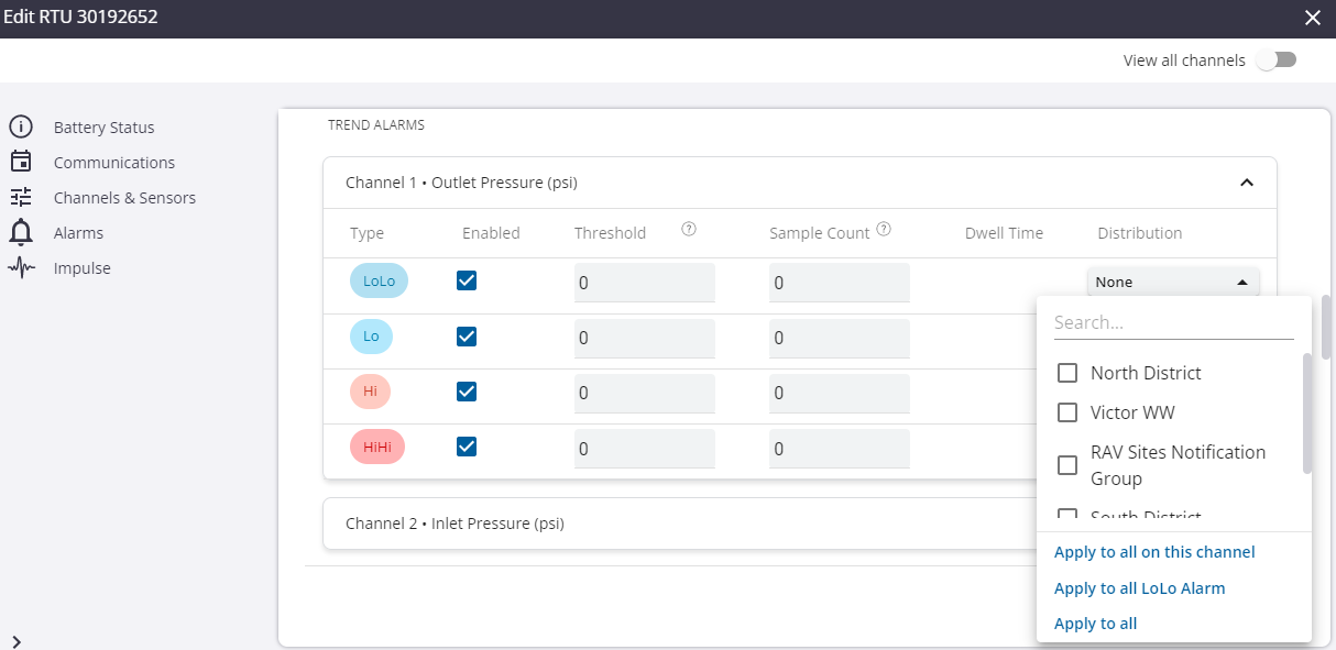
Limits for alarms can be set or changed using the Trimble Unity web app.
- In the Alarms section, select the Enabled check box to enable an alarm. An alarm must be enabled before you can modify other fields for the alarm.
- Enter the Threshold of the alarm. Note that Event channels do not include a threshold setting, but instead allow alarms to be triggered on either the Open or Closed state. Closed alarms are reported as Lo alarms in the alarm history and dashboard while Open alarms are reported as Hi alarms.
- LoLo: the alarm is triggered when the reading is equal to or less than the threshold.
- Lo: the alarm is triggered when the reading is equal to or less than the threshold.
- Hi: the alarm is triggered when the reading is equal to or higher than the threshold.
- HiHi: the alarm is triggered when the reading is equal to or higher than the threshold.
- Enter the Sample Count of the alarm.
- Sample Count: the number of consecutive samples in the alarming threshold required before the alarm is triggered.
- The Dwell Time calculates how much time it takes, based on the threshold, sample rate, and sample count, before the alarm is triggered. This value must be a whole number of seconds and will be rounded up to the nearest second when working with RTUs that support sub-second sampling.
- Click the Distribution drop-down list to select groups of users to receive the alarm notifications.
- Click Update.
Pressure impulses can be configured on impulse-enabled RTUs. This is done from the RTU details panel.
|
|
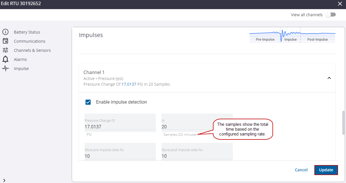
- In the Impulses section, click Enable impulse detection to activate the impulse fields.
An impulse capture is triggered when the difference between the maximum pressure reading minus the minimum reading, during the trigger window, is greater than or equal to the pressure change configured. The impulse capture completes after the trigger is no longer active, meaning the maximum reading minus the minimum reading is less than the pressure change configured for the trigger window.
There are four parameters to set for impulses:
- Pressure Change of: the minimum pressure change required to trigger an impulse capture.
- In: the trigger window or the maximum number of samples considered when detecting an impulse.
- Store Pre Impulse Data For: the number of samples saved before the impulse trigger.
- Store Post Impulse Data For: the number of samples saved after the impulse trigger is no longer active.
- Enter information in the Pressure Change of, In, Store pre impulse data for, and Store post impulse data for fields.
- Click Update to save the changes.
NOTE: The RTU configuration updates will be applied to the RTU the next time the RTU calls in.