Configure RTU Channels
RTU channels can be enabled and configured using the Trimble Unity web app. Various settings can be updated, including sampling and recording intervals, channel type, range, and scaling.
 NOTE: The number of channels that can be configured depends on the type of RTU.
- Click the RTU you want to configure from the RTU list.
- Click Edit on the RTU details panel.

- Toggle the View all channels switch to view all the channels.
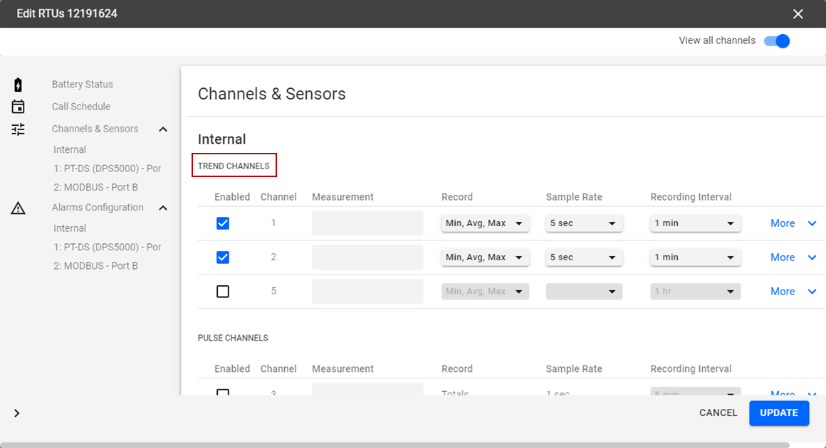
In the Channels and Sensors section, the channels are listed as well as the channel details.
The three available channel categories are Trend Channels, Pulse Channels, and Event Channels.
NOTE: The channel fields are preconfigured based on the sensor type, but can be customized if needed.
Trend Channels: these channels sample electric current or voltage from the connected sensors and translate into data and measurements such as water level, pressure, and flow. The three configurable parameters of a trend channel are statistical data to record (average, minimum, and maximum), how often to sample from the sensor, and how often to save or record the statistical data.
- Enabled: the channel is enabled.
- Channel: the channel number is listed.
- Measurement: the measurement of the channel.
- Record: the measurements being recorded. Click the Record drop-down list to select the data you want to record.
- Sample Rate: how often you want the sensor to take a sample of the measurement. Click the Sample Rate drop-down list to select how often the sensor takes a sample.
NOTE: The sample rate is the rate at which the input signal is sampled. The sample rate requirements vary widely depending on the application. The most rapid sample rate available is once per second (except for sensors such as hydrant pressure recorders with impulse detection, which sample at a much higher rate). Note that the list of available sample rates is dependent upon the currently selected recording interval for the selected channel. Therefore, the longest sample rate is always equal to the currently programmed recording interval.
 BEST PRACTICE: If you are only using battery power to run your recorder, select the slowest sample rate that is consistent with your input signal. Battery life is dependent upon sampling frequency and higher frequency sample rates will always shorten the battery life.
- Recording Interval: how often the data is recording the samples. Click the Recording Interval drop-down list to select how often the data records the samples. That is, how often it records the chosen measurements. For example, for each recording interval it will record the average, minimum, and maximum for the samples taken during the recording interval.
NOTE: The recording interval is the frequency at which selected statistics are computed and stored into the recorder's permanent memory. You can select different recording intervals for each channel and the list of available recording intervals is dependent upon the currently selected sample rate for the selected channel. Recording intervals are always multiples of the sample rate.
BEST PRACTICE: If you are only using battery power to run your recorder, select the slowest recording interval that is consistent with your application as battery life is dependent upon the recording interval. Higher frequency recording intervals will always shorten the battery life.
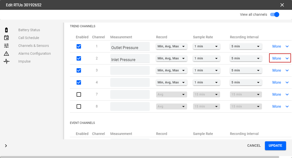
- Click More to open more configurations and settings for the channel.
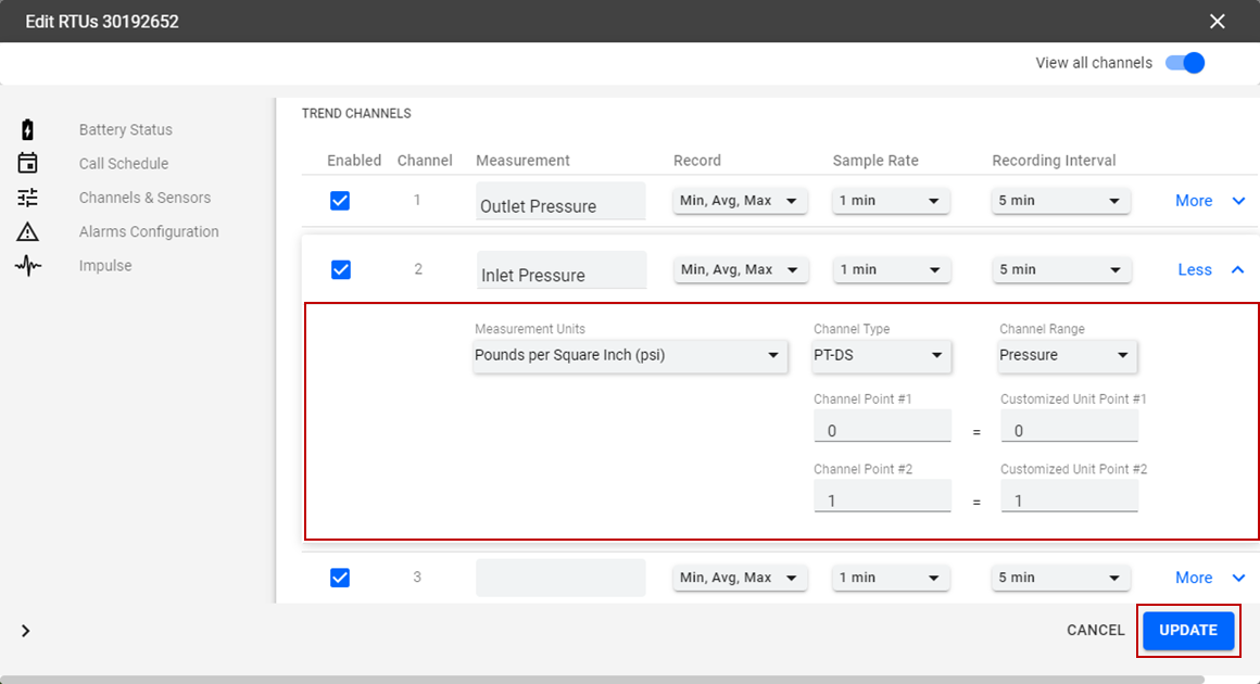
- Click the Measurement Units drop-down list to select the measurement unit for the channel.
NOTE: The channel fields are configured based on the sensor type, but can be customized if needed.
- Select a Channel Type from the drop-down list.
NOTE: Depending on the type of recorder you are working with, it may be possible to change the channel type for a specific channel. For example, channels 1–4 of the R-3307 recorder can be programmed to be either voltage channels or current channels. For other recorders such as HPR-32A, which are measurement-type specific, there is only one channel type option: pressure. When changing channel types, if there are any required hardware modifications, a message alerts you of the necessary changes.
In the case of the R-3307 and the R-3314, changing from voltage to current requires that a switch setting be changed on the recorder. If the switch setting does not match the programmed channel type (for example, if the switch position is set to volts, but the software setting of the channel is set to current), then the channel does not record any data. R-3000 pulse channels increment their pulse counter on the occurrence of a high (switch open) to low (switch closed) transition.
 IMPORTANT: If the channel type is changed, the scaling for the channel must be modified as the old scaling information becomes invalid.
- Select a Channel Range from the drop-down list.
NOTE: Depending on the channel type, it may be possible to change the channel range of a selected channel. The possible ranges available are displayed in a drop-down list from which you can select the desired setting.
IMPORTANT: If the channel range is changed, the scaling for the channel must be modified as the old scaling information becomes invalid.
- Update the Channel Point and Channel Range fields, if necessary.
NOTE: Channel scaling determines how the actual analog signal (for example, voltage or current) is translated into a recognizable engineering unit as defined in the Measurement Units field (for example, PSI for pressure). The scaling is determined by supplying two points mapping a channel output value (for example, mV) to the relevant measurement value (for example, PSI). Typically, the two values supplied will mark the range of the channel (for example, 0–1 volts).
For pulse channels, the difference is you are counting the number of times a switch is opened or closed so you need to associate each time the switch is operated with a quantity of the defined measurement unit. For example, the "pulse" on a rain gauge is determined by an occurrence of the rain gauge bucket tipping and emptying. If a tipping occurrence is associated with a measurement of one inch of rain, and there are two occurrences of the tipping within a half hour recording interval, the total in the recording interval will be two inches, or will equate to a rate of four inches per hour, given the half-hour recording interval.
IMPORTANT: If the channel point or range is changed, the scaling for the channel must be modified as the old scaling information becomes invalid.
- Click Update.
The Channels and Sensors section on the RTU details panel shows the updates.
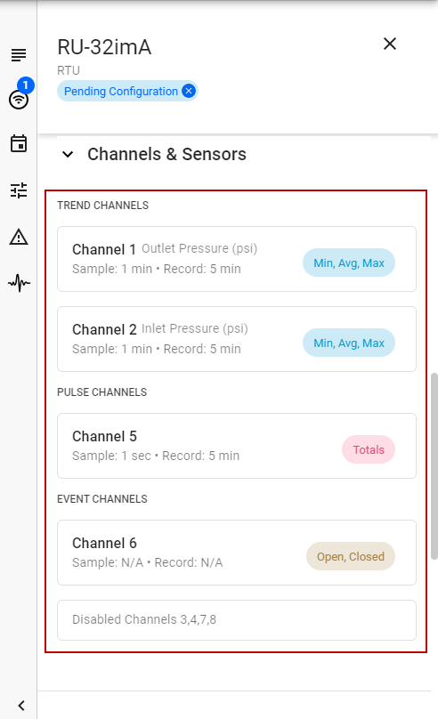
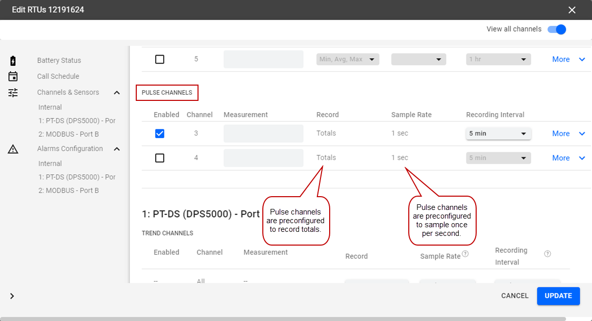
Pulse Channels: these channels count pulses from sensors which translate the totals into data and measurements such as total rain fall or total flow from water meters. The parameter to configure is how often to record the total pulses.
- Enabled: the channel is enabled.
- Channel: the channel number is listed.
- Measurement: the measurement of the channel.
- Record: the measurements being recorded. This is preconfigured to record Totals.
- Sample Rate: how often you want the sensor to take a sample of the measurement. This is preconfigured to sample once per second.
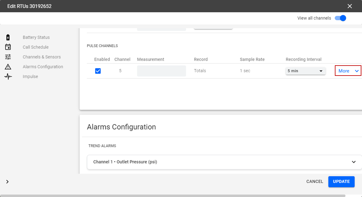
- Recording Interval: how often the data is recording the samples. Click the Recording Interval drop-down list to select how often the data records the samples.
NOTE: The recording interval is the frequency at which selected statistics are computed and stored into the recorder's permanent memory. You can select different recording intervals for each channel and the list of available recording intervals is dependent upon the currently selected sample rate for the selected channel. Recording intervals must be multiples of the one sample per second sample rate.
BEST PRACTICE: If you are only using battery power to run your recorder, select the slowest recording interval that is consistent with your application as battery life is dependent upon the recording interval. Higher frequency recording intervals will always shorten the battery life.
- Click More to open more configurations and settings for the channel.
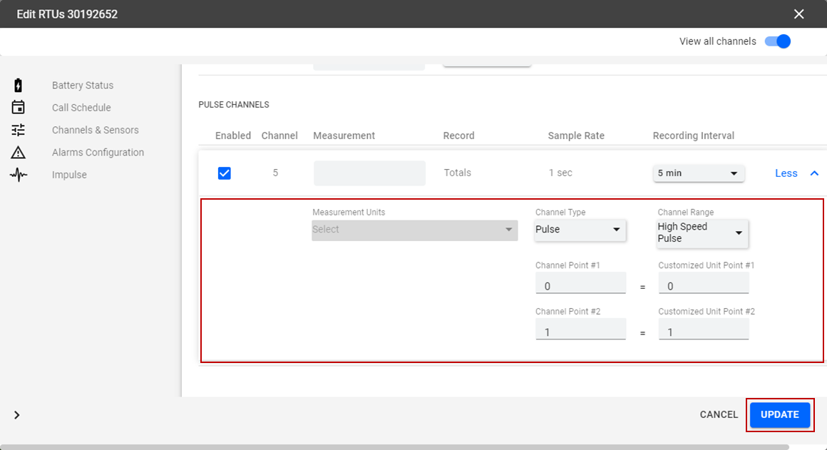
- Select a Channel Type from the drop-down list.
NOTE: Depending on the type of recorder you are working with, it may be possible to change the channel type for a specific channel. For example, channels 1–4 of the R-3307 recorder can be programmed to be either voltage channels or current channels. For other recorders such as HPR-32A, which are measurement-type specific, there is only one channel type option: pressure. When changing channel types, if there are any required hardware modifications, a message alerts you of the necessary changes.
In the case of the R-3307 and the R-3314, changing from voltage to current requires that a switch setting be changed on the recorder. If the switch setting does not match the programmed channel type (for example, if the switch position is set to volts, but the software setting of the channel is set to current), then the channel does not record any data. R-3000 pulse channels increment their pulse counter on the occurrence of a high (switch open) to low (switch closed) transition.
IMPORTANT: If the channel type is changed, the scaling for the channel must be modified as the old scaling information becomes invalid.
- Select a Channel Range from the drop-down list.
NOTE: Depending on the channel type, it may be possible to change the channel range of a selected channel. The possible ranges available are displayed in a drop-down list from which you can select the desired setting.
IMPORTANT: If the channel range is changed, the scaling for the channel must be modified as the old scaling information becomes invalid.
- Update the Channel Point and Channel Range fields, if necessary.
NOTE: Channel scaling determines how the actual analog signal (for example, voltage or current) is translated into a recognizable engineering unit as defined in the Measurement Units field (for example, PSI for pressure). The scaling is determined by supplying two points mapping a channel output value (for example, mV) to the relevant measurement value (for example, PSI). Typically, the two values supplied will mark the range of the channel (for example, 0–1 volts).
For pulse channels, the difference is you are counting the number of times a switch is opened or closed so you need to associate each time the switch is operated with a quantity of the defined measurement unit. For example, the "pulse" on a rain gauge is determined by an occurrence of the rain gauge bucket tipping and emptying. If a tipping occurrence is associated with a measurement of one inch of rain, and there are two occurrences of the tipping within a half hour recording interval, the total in the recording interval will be two inches, or will equate to a rate of four inches per hour, given the half-hour recording interval.
IMPORTANT: If the channel point or range is changed, the scaling for the channel must be modified as the old scaling information becomes invalid.
- Click Update.
The Channels and Sensors section on the RTU details panel shows the updates.
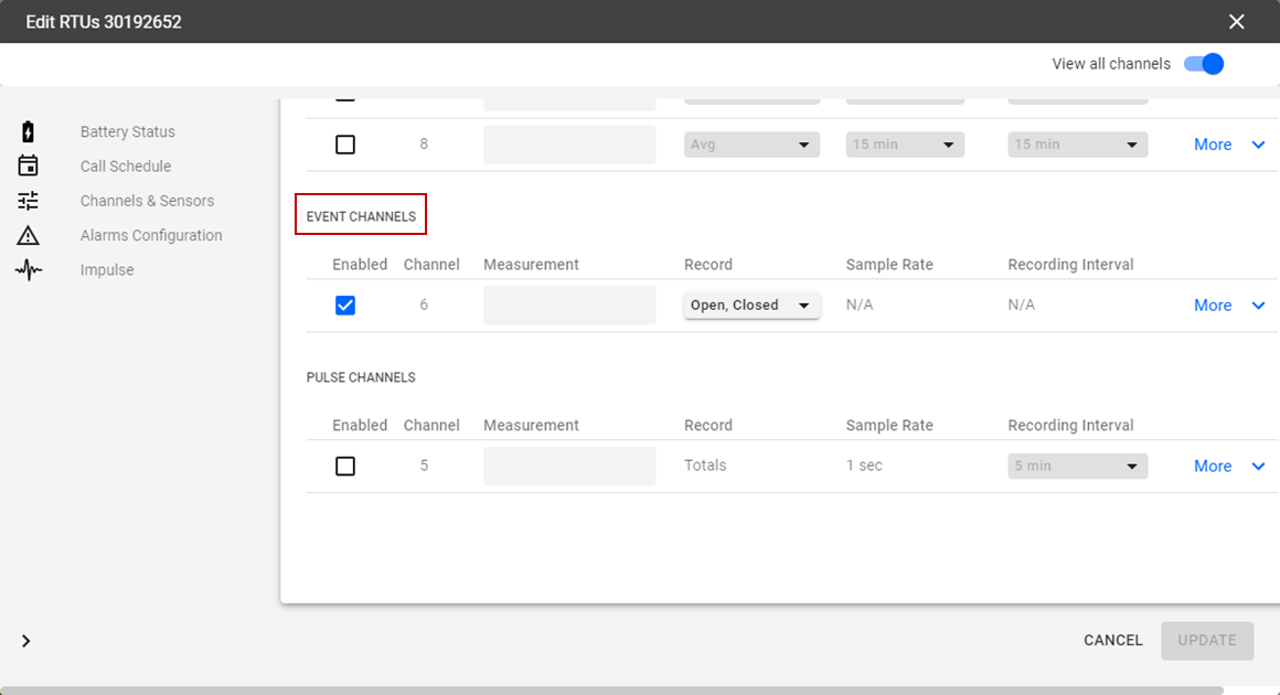
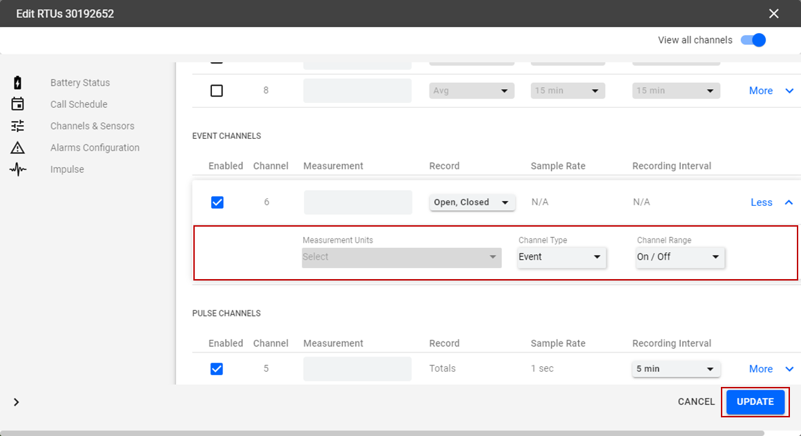
Event Channels: these channels do not record trending data over time. Rather, they state changes when switches close and open, and the time these events occur. These channels are typically used to alarm and monitor events such as pump run cycles, flow switches, and power failure. The parameter to configure is what events the RTU will record.
- Enabled: the channel is enabled.
- Channel: the channel number is listed.
- Measurement: the measurement of the channel.
- Record: the measurements being recorded. Click the Record drop-down list to select the data you want to record.
- Sample Rate: N/A
- Recording Interval: N/A
- Click More to open more configurations and settings for the channel.

- Select a Channel Type from the drop-down list.
- Select a Channel Range from the drop-down list.
- Click Update.
The Channels and Sensors section on the RTU details panel shows the updates.